PCal Photodiode Board
- Document #:
- LIGO-D1300210-v7
- Document type:
- D - Drawings
Other Versions:
| LIGO-D1300210-v6
28 Jul 2021, 21:47 |
| LIGO-D1300210-v5
09 Jul 2021, 13:13 |
| LIGO-D1300210-v4
29 Jun 2021, 14:45 |
| LIGO-D1300210-v3
22 Sep 2014, 14:12 |
| LIGO-D1300210-v2
24 Jun 2014, 16:12 |
| LIGO-D1300210-v1
24 Jul 2013, 10:56 |
- Abstract:
- We have decided to generate separate drawing numbers for the two types of photodetector transimpedance amplifiers used for the Pcal laser power sensors.
This filecard is for the units installed at the end stations that have bothdifferential outputs going to the and single-ended monitor outputs. The filecard for the circuit boards for the PD transimpedance amplifiers for LIGO Pcal power sensors going forward (and being implemented in both Virgo and Kagra) is D2100733. The overall gain at the single-ended buffered output is 5 volts per 1 watt laser power at 1047 nm input into the integrating sphere and detector spacer assembly. The differential output is twice this value, about 10 V (differential) per watt. The InGaAs responsivity is about 0.8 V/W and the attenuation of the integrating sphere and detector spacer is about 1/21,000.
- Files in Document:
-
- Circuit diagram in .pdf format (D1300210-v7.pdf, 118.8 kB)
- Other Files:
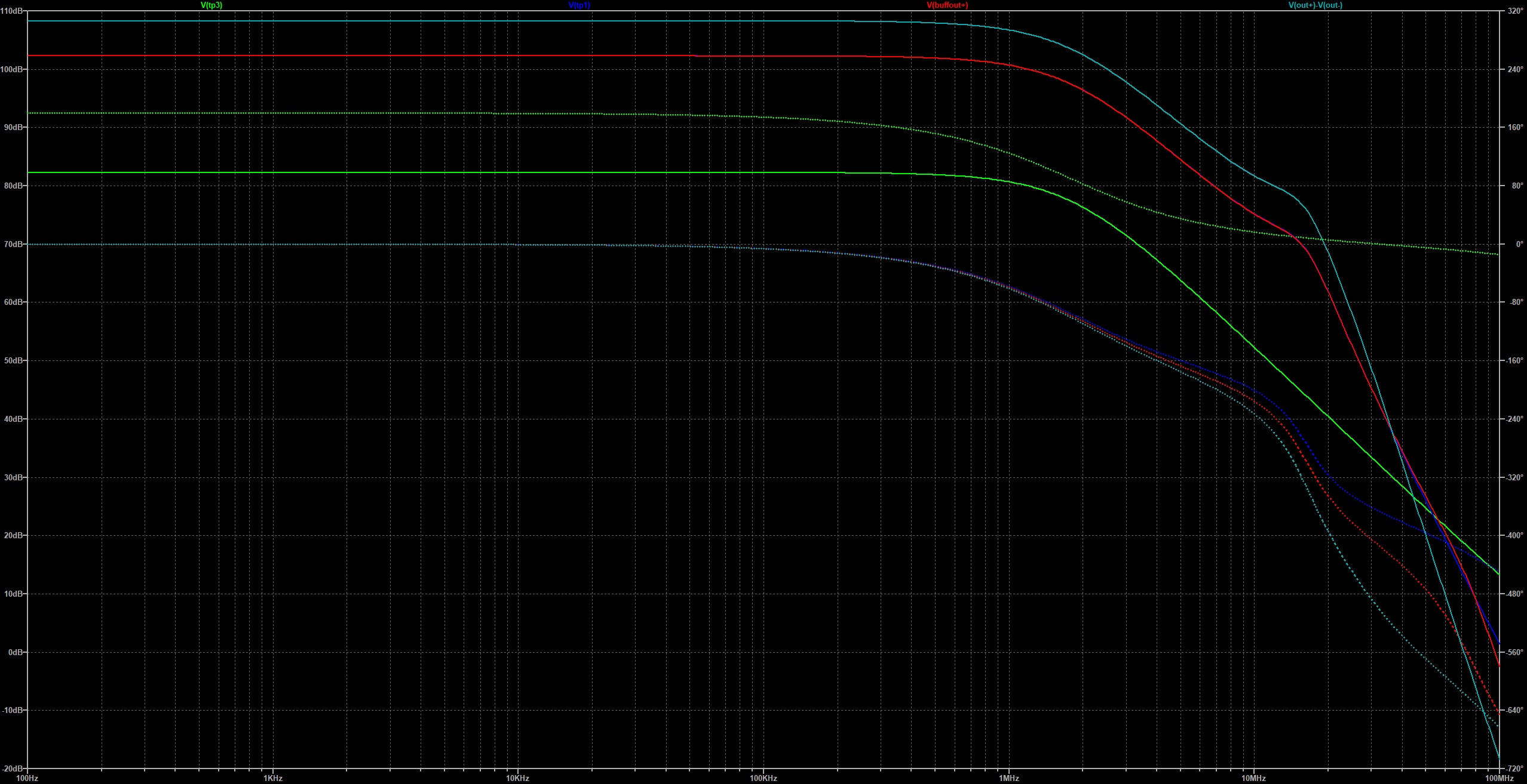
- PSpice modeling results (D1300210v7.jpg, 670.7 kB)
- ICS/JIRA Record:
-
- ICS_LINK
- Topics:
- Authors:


- Keywords:
- PD PCal Photodiode Photon Calibrator
- Notes and Changes:
- See D1300210-v4 for previous version of this board.
Previous abstract for v6 version:
This is the board that goes in the PCal Photodiode Housing, D1300103 There are two types of boards that have been (probably mistakenly) combined in this file card using different versions. There really should be two "types."
Type 1, captured in v4, is the board that we use at the end stations for the Tx and Rx power sensors. It has a differential output. Type 2, captured in v5, is the board we use for the Pcal transfer standards (working standards, gold standards, and transfer standards). It has a single-ended output. Going forward, in order to use this single file card, I suggest we continue to designate whether it is a Type 1 or Type 2 board in the "Notes and Changes" field. See word document for details on changes made to V6 board.
- Related Documents:
- LIGO-D1300103: aLIGO Pcal Photodetector Assembly
- LIGO-D2100733: Pcal transfer standard transimpedance amplifier circuit board
- Referenced by:
- LIGO-T1400031-v1: PCal Photodiode Board Test Procedure
- LIGO-T1400152-v1: Characterization of P-Cal PD Circuit Boards
- LIGO-D2100733-v1: Pcal transfer standard transimpedance amplifier circuit board